

Stability vs. Fill-Time in Proportional Control Applications
Category:
Achieving optimal speed and stability in pressure control applications is an intricate dance that requires understanding, preparation, and patience. Too often, an inaccurately sized proportional controller finds itself tasked with the impossible. Once installed into a process, the bankrupt controller may cause weeks of delay as massive amounts of time are wasted troubleshooting. However, this can be prevented by ensuring optimal specification of your proportional control product. In this paper, we will help you better understand how to accomplish this by explaining the two major factors that impact the performance of your controller—stability and fill-time.
Proportional pressure controllers come in all shapes and sizes, with varying capacities to manage specific pressures and achieve vastly different flow rates. They operate in every industry to help manufacture components, final test products, and support analysis. Applications that require proportional pressure control span in nuance from very high pressures with high flow rates to very low pressures with low flow rates and everywhere in between. Typically, a controller's accuracy, resolution, or repeatability is the basis for why it is—or is not—selected to control a process. However, every process has an implicit expectation that the desired pressure remains reasonably stable at the desired point of control. In most processes, instability equals unpredictability, inducing production delays, poor data acquisition, and loss of confidence in analytical devices.
Fill-Time
The principal factor influencing pressure control stability is fill-time or speed. However, numerous conditions can affect fill-time, such as temperature, downstream volume, line restrictions, inlet pressure, and PID settings. Each of these conditions also contributes to varying impacts related to the specific pressure and flow range in the process. For this reason, this paper considers stability versus fill-time as it relates to pressure reducing, low-flow high-technology applications employing proportional controllers with integrated PID tuning capabilities.
There are countless reasons a higher pressure is reduced and controlled in a process. Some applications reduce pressure slowly to control the precise dispensing of a viscous fluid while others reduce pressure to inflate products as quickly as possible. Fill-time references the speed or time required to reduce the higher pressure to the desired controlled setpoint. Speed is not fast or slow—it is merely what is possible with the available equipment under the specific conditions. The physics of fluid dynamics dictate the speed at which a compressed gas travels through its prescribed path. For this reason, the path and proportional controller must both physically support the necessary fill-time expected for success in a process and be tuned correctly for the particular operating conditions.
Stability
The perfect electronic proportional pressure control device would deliver the desired output pressure instantly and remain stable for as long as specified, while continuously adjusting its output in response to dynamic conditions to sustain pressure stability—within a stated tolerance—over time. This perfect scenario (except for instant pressure delivery) is not only possible, but plausible. However, it is generally never realized due to the lack of understanding around the physics of how compressed gas flows.
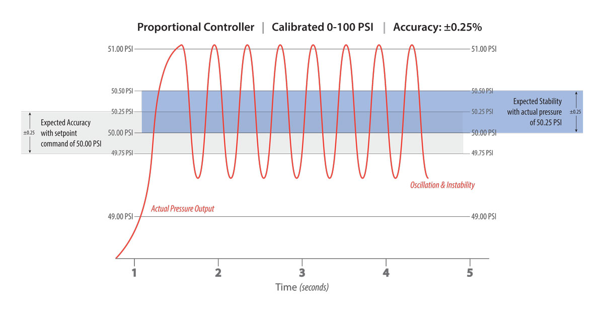
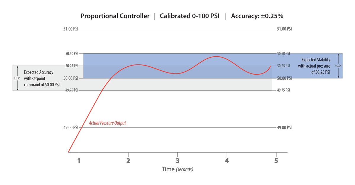
It is important to note that perfect stability is a myth. An acceptable amount of instability must be anticipated and expected. This range should be known and measurable, and ordinarily equates to the device's factory-defined accuracy specification. This specification references the smallest change in pressure the internal sensor is capable of detecting. For example, a device calibrated 0-100 psig may have an accuracy spec of ±0.25% of full-scale calibration. With a set point of 50 psig, we should expect output pressure to be between 49.75 and 50.25 psig (± 0.25 psig). Assuming the actual pressure lands on the upper limit of 50.25 psig, we should expect output pressure to remain stable within ± 0.25 psig, or from 50.00 to 50.50 psig. Any pressure drift inside of this range is undetectable by the sensor, and hence within tolerance for stability.
Spikes of instability are likely to occur, especially if a process is dynamic and under continuous flow. These fluctuations could result from unexpected backpressure, an increase in downstream demand, sudden change of inlet pressure, or significant temperature changes. However, an appropriately sized and tuned proportional controller should adjust and return to stable output after such spikes. When a variation becomes a rapid or slow oscillation, the system is unstable, and conceivably the following scenario is in play.
How PID Settings and Orifice Size Affect Stability in Proportional Control
When discussing low-flow high-technology applications, it is typical for the downstream volume to be extremely small, sometimes less than 1 in3. With a limited amount of volume, the proportional controller must have the correct PID settings, and the internal valves should employ the optimal orifice size to prevent the closed-loop electronic pressure control device from entering into a cycle of oscillation. The most common reason for oscillation in this situation is due to improper valve sizing allowing too much air to pass over the sensor element. In general, achieving pressure quickly with quick fill-times is ideal. However, in this scenario, the fill-time or flow rate of the process is too fast to allow for stable pressure control. When the device receives a setpoint command, the inlet valve opens to allow a slug of compressed air to pass over the sensing element. Due to the restricted volume, the slug of air slams into the space, causing pressure to overshoot the setpoint. Before pressure can settle, the reflected slug of air is detected by the sensing element, prompting the exhaust valve to open and discharge excess pressure from the volume, resulting in immediate undershoot. This cycle of oscillation can loop continually at speeds of 2 to 4 Hertz.
There are two ways to eliminate the dreaded oscillation loop related to a small volume in conjunction with over-sized valves allowing too much flow. First, it may be possible to tune out the oscillation by modifying the device's PID settings. When a device is specified correctly for the amount of downstream volume, and there is instability or oscillation of the controlled pressure, the PID values are likely set too aggressively and require adjusting. Both the Proportional and Integral settings require a dampening, or reduction of values, until the anomaly disappears. This adjustment is effective within a relatively small window and when breached, instability and adverse effects to accuracy and resolution emerge. Secondly, the orifice size or flow rate of the internal solenoid valves can help stabilize the application when a limited amount of volume exists and the PID settings require extreme dampening. In this case, implementing smaller orifices that produce lower flow rates prevents such an aggressive slug of air from passing over the sensing element, mitigating over and undershoot.
Reducing the flow to eliminate instability is a typical response to small downstream volumes. However, it is equally common to demand more flow and a faster setpoint realization. The same techniques mentioned above apply in reverse to generate faster response and more flow, but one factor is paramount to understanding what is possible and what is not. No matter how big the valve orifice's are, or how much differential pressure is available, the smallest restriction in the process dictates the maximum possible flow rate. For example, basketball manufacturers are continually seeking to improve fill-time and increase production. However, as everyone knows, the basketball inflation hole is tiny compared to the volume inside the ball. The recommended 8 psig can only travel so fast through the available orifice. The smallest restriction always dictates the speed. In most applications, the ideal solution is for the valves inside the proportional controller to possess the smallest restriction in the process. By implementing the ideal physical restriction, the PID settings can be tuned for optimal aggression, producing the perfect scenario to achieve the highest accuracy, resolution, and stability in the process.
The dynamics of stability versus fill-time, balanced with a device's physical characteristics, ultimately determine if sacrifices must occur in closed-loop pneumatic applications. Therefore, it is imperative to understand the specifics of a particular process, the pressures involved, available downstream volumes, and actual flow rates needed before selecting a proportional controller. For assistance with the specification process, questions about stability and fill-times, or to learn more about how Clippard's Cordis Series can improve your process, please contact Clippard or your local Clippard distributor.
Related Content
|
Related Products |
||||
Cordis Pressure Controls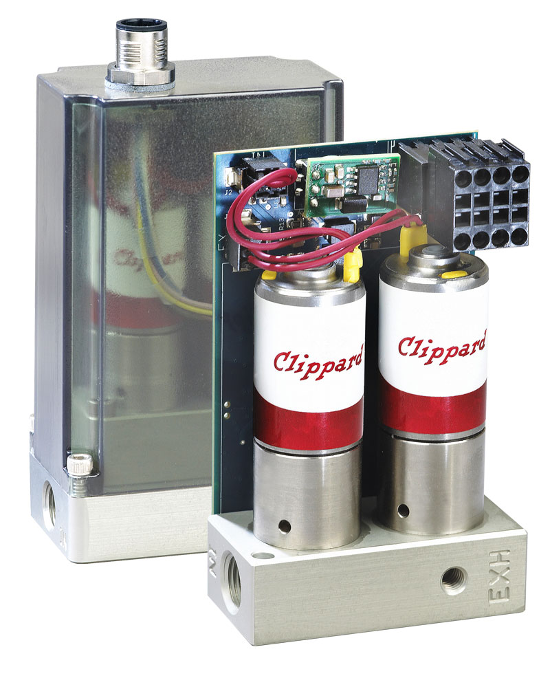 |
||||


