
Pressure Control vs. Flow Control
Category:
Pneumatic fluid power is a universal and cost-effective method for delivering energy to instrumentation and industrial processes. In cooling applications, fluid flows past something to carry away heat. In an analytical instrument, the velocity of a carrier gas may be a critical timing mechanism. Gas pressure can mitigate sleep apnea. In each of these cases, fluid is controlled to achieve a particular outcome. The power delivered to these processes requires pressure control or flow control.
How are pressure and flow control achieved? What are ideal products for controlling fluid power and how do they affect the outcome? The answer to those questions begins with a definition of pressure and flow and an understanding of open and closed-loop systems.
Pressure vs. Flow—The Basics
Pressure is force. It acts in all directions, all at once and with the same power. The amount of force a pressure exerts is directly related to the area in which the pressure is contained (pressure = force/area). Pressure does not require directional input, like a hammer on a nail. It merely needs to be routed and contained within a specific operation for reliable power transmission. Pressure can exist in a vacuum (negative pressure) while moving through a conduit (underflow) or deadheaded within a static chamber.
Flow is the movement of pressurized fluids between volumes of varying (differential) pressures. Pressurized fluid always moves from higher pressure to lower pressure. Without a pressure differential, the fluid is stagnant, and the system is absent of flow. Flow (in terms of fluid dynamics) breaks down into two distinct measurable rates: volumetric flow rate and mass flow rate.
All gas has mass. The 3-dimensional space containing gas molecules (mass) is the volume. As temperature and pressure changes, so does the container (volume). The volumetric flow rate measures the space occupied by a particular gas over time. Standard units of measure include liters per minute (LPM) and cubic feet per minute (CFM).
The mass of an object has a finite molecule count. Gasses can compress their mass into smaller and smaller volumes to create pressure. The mass flow rate measures the number of molecules passing through a single point. Standard units of measure are kilograms per minute or pounds per minute.
Open-Loop vs. Closed-Loop Fluid Control
Controlling fluid to a fluid power process infers the ability to set or modify the amount of energy to that process. Numerous techniques and products are available for regulating fluid power. However, they all boil down to one of two concepts: open-loop control and closed-loop control.
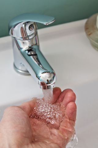
A standard faucet is an example of an open-loop system. Adding your hand under the faucet for feedback would make it a closed-loop system.
In open-loop control schemes, a controller provides an input action to generate an output response; the result of the operation is independent and unknown to the controller. It is a cause and "blind" effect relationship. An example of an open-loop system is a standard water faucet. The controller (hand) turns the handle to open a valve (input action). The valve opens and (hopefully) allows water to flow from the faucet. Whether or not water flows is unknown to the valve and the hand (controller). Hence, the system is considered open. For obvious reasons, open-loop systems are less accurate, less repeatable and (generally) less costly.
In closed-loop control schemes, the input action supplied by the controller is dependent on feedback from the process it intends to control. Using the faucet example, assume a person wants to wash their hands at an "acceptable" temperature. The controller (hand) turns both the hot and cold valves to enable water to flow from the spigot. The other hand is placed under the running water to judge (measure) the temperature. The brain interprets the water temperature as too hot or too cold, and this feedback is furnished to the original hand (controller) to modify the input action. Acceptable temperature is now maintained and easily adjusted when changes occur. In the simplest terms, if the output (result) is directly related to the input (action) via feedback, the system is closed-loop, if not it is considered open-loop.
Mechanical & Electronic Flow Control
Flow control valves control the volumetric rate of the fluid that flows through them. Generally, changing the size of the orifice is how the flow rate is set and adjusted. A tapered needle moving in and out of an orifice or opening and closing the gap inside a ball valve changes this rate. Volumetric flow controls are typically used to control velocity—for example, the extension and retraction speed of a cylinder or the rate at which a fluid is sprayed or dispensed.
Mechanical flow control valves are some of the most commonly used fluid control valves on the market. They operate in a wide variety of markets, from everyday household items (such as the water faucet above) to precision medical applications. Some standard industry terms for mechanical flow controls are needle valves, ball valves, and meter-in/meter-out valves, among others. Mechanical flow controls are available with both open-loop and (in some rare applications) closed-loop control.
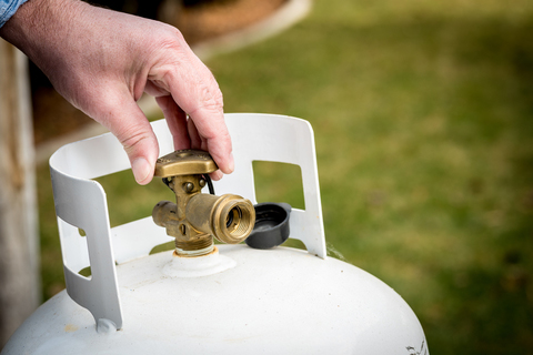
Propane tanks come standard with open-loop control. Pressurized propane is released when the valve opens, and the rate of flow is directly related to the size of the opening. The flow rate is at its highest when the tank is full. Over time, the pressure in the tank decreases and the differential (between tank pressure and outlet pressure) contracts, reducing flow. Closed-loop mechanical flow controls are uncommon, as it is difficult to send a feedback signal to a mechanical valve. However, a straightforward example would be the flapper valve on a toilet, which closes to allow less flow into the tank as the float rises, ultimately closing when the tank is full.
 Example of open-loop control. |
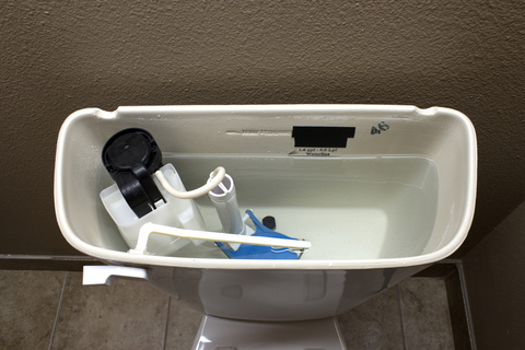 Example of closed-loop control. |

A medical application where two gases blend at precise ratios for delivery to a patient requires high precision and must be a closed-loop system.
In many instances, the process demand fluctuates, creating instability and making repeatable flow control impossible with mechanical flow valves. In these situations, variable control of the flow using an electrical input becomes necessary. The industry term for these controls is proportional valves. Proportional valves come with a wide variety of actuation methods, for example, a voltage, current, step-input or digital input. They can be designed into a control system that is closed-loop, with feedback from an electronic flow meter, or open-loop. These valves are ideal for applications where the flow requirement is continually changing.
Closed-loop flow control systems generally result from a requirement for precision. A remote-controlled propane fireplace does not require high precision—there only needs to be a noticeable difference between small and large flames—and can, therefore, be an open-loop system. However, a medical application where two gases blend at precise ratios for delivery to a patient requires high precision and must be a closed-loop system. In the case of mixing gases, this may even require a mass flow meter rather than a volumetric flow meter to ensure that the ratios are correct.
Mechanical & Electronic Pressure Control
Pressure control products are designed to control the amount of force produced by a fluid system. Pressure controls are most commonly known as pressure regulators and, like flow controls, are available in both manual and electronic variations. Pressure regulators are not designed to control flow rates. Although pressure regulators used in flowing systems inherently affect the flow by controlling the pressure, they are not designed to act as flow controllers.
Pressure regulators are by nature closed-loop, meaning they must be able to sense downstream pressure (or upstream for backpressure regulators) via a feedback loop that automatically adjusts to maintain setpoint. When the output of the regulator senses that the pressure has dropped below a predetermined point, the regulator opens and allows more pressure though. Once the pressure reaches the setpoint, the regulator closes and no longer allows flow.
Mechanical pressure regulators come in a variety of styles, but every mechanical regulator has three essential elements:
-
Restriction - A valve that provides an adjustable restriction to the flow, typically a poppet style valve
-
Load - Part that drives the restriction valve to set the desired outlet pressure, usually a piston or a diaphragm
- Reference - Force that determines when the inlet flow equals the outlet flow to provide a constant outlet pressure, often a spring
The use of the reference force is what makes mechanical pressure regulators closed-loop. Without this feedback, the pressure would change every time downstream flow demand changed.
There are two common types of mechanical pressure regulators: piston style and diaphragm style regulators. Piston style regulators tend to be robust and hold up well in applications where ruggedness is a concern. However, they do experience some hysteresis as a result of the friction between the piston seal and the regulator body. They are not for use in applications where the outlet pressure must be held to a tight tolerance. Piston style regulators are excellent for applications where durability is more important than accuracy. For example, if your shop air is 90 psig, but your valve rating is 60 psig, a piston regulator is useful to knock the pressure down so that you do not damage the valve.
If the regulator needs to control low pressures or high precision, a diaphragm style regulator is recommended. Diaphragm regulators employ a disc-shaped diaphragm, usually made of an elastomer, to sense pressure changes, which eliminates the friction experienced by the piston style regulators. The reduced friction results in better precision and accuracy, making these regulators ideal for applications requiring precise, repeatable pressure control; this may include medical, semiconductor, and most applications in life sciences.
Mechanical pressure regulators are an excellent option for applications where upstream pressure and flow see only minor fluctuations and the user wants to "set-it-and-forget-it." However, just like with flow controls, some applications may demand a variable pressure output, remote control, automation, data acquisition or better repeatability, which would require an electronic pressure regulator (EPR).
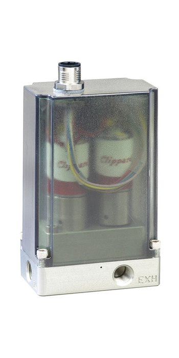
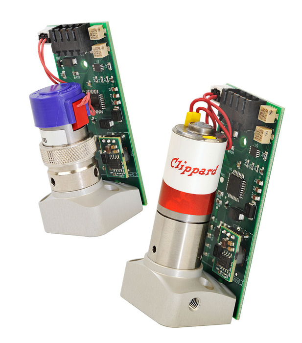
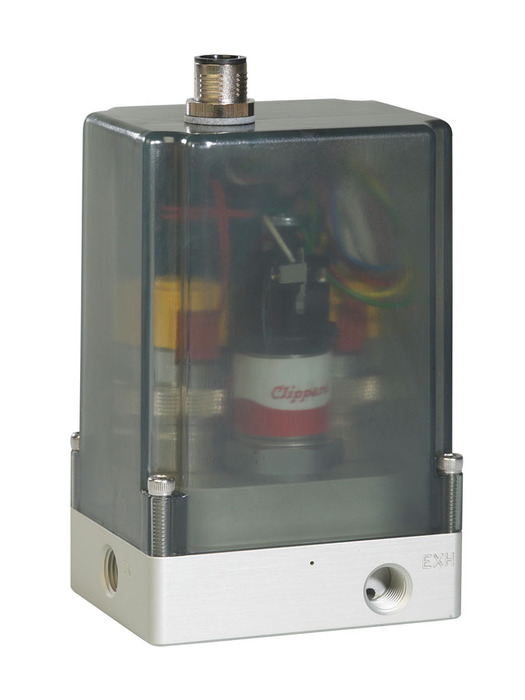
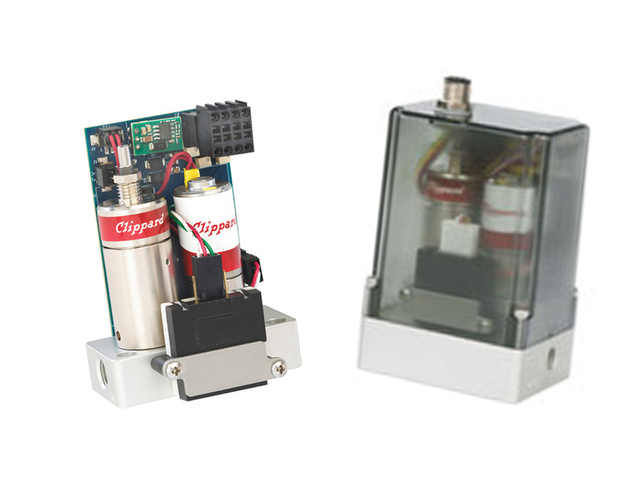
The most common configuration for an electronic pressure regulator (EPR) is 2 valves and a sensor. One inlet valve, one exhaust valve and an internal pressure transducer actively measuring downstream pressure and continually providing feedback to an analog or digital circuit board. A command signal generator (usually a PLC) is used to supply the EPR with a command setpoint. For example, a 0-10 VDC signal (many options exist) directly equating to the calibrated range of the EPR, in this case, 0-100 psig. A volt command anywhere between zero and ten volts results in the equivalent (as a percentage of full scale) pressure output. For example, with a 5 VDC (50%) command, the inlet valve opens to allow pressure downstream. The inlet valve remains open until the internal sensor says, "Hey, I measure 5 VDC (50 psig), you can close now". If flow increases downstream, pressure drops and the sensor instantly senses the deviation from the 5 VDC command. The inlet valve opens again until the sensor is satisfied. This relationship and automated process extends throughout the full range and is known as linear and proportional closed-loop electronic control.
Choosing the Right Fluid Control
There are many different fluid controls to choose from when designing a pneumatic system. Understanding if you are trying to control force (pressure) or speed (flow) is the first step to selecting the fluid control that is right for you. Additionally, your application dictates whether you can use a mechanical control or if you need electronic control, and whether it can be open-loop or must be closed-loop.
If you have questions about what flow control you should be using for your application, contact tech@clippard.com for additional support.
Related Content
- Cordis Series Electronic Controls
- Practical PID Process Dynamics with Proportional Pressure Controllers
- Cordis Pressure Controls FAQ