
Modular Circuit Assembly Tips
Category:
 |
Versatility is the key when it comes to
Clippard’s Minimatic® Modular Valves.
Available in an unlimited variety of directional, flow, pressure and special control valves - each in a valve body designed to mount and link together with a simple piping system.
The piping system eases assembly and plumbing, resulting in reduced labor costs, errors in installation, and the potential for plumbing leakage. In addition, multiple valve elements
can be contained in a single body; providing incredible flexibility and variety to accomplish
a myriad of control challenges. The Minimatic modular valves are the supreme “Plug and
Play” devices for pneumatic applications.
|
|||
|
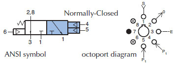
The first step in building a modular circuit is designing the pneumatic circuit using ANSI or simplified symbols.
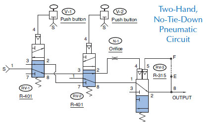
We have chosen the Two-Hand, No-Tie-Down Circuit for this demonstration. |
 |
|||
|
Specifications for the R-315 modular valve |
The next step is selecting the octoport diagram for each modular valve. Each Clippard modular valve (R-series) has its own unique octoport diagram which is shown to the right of the ANSI symbol.
|
|||
|
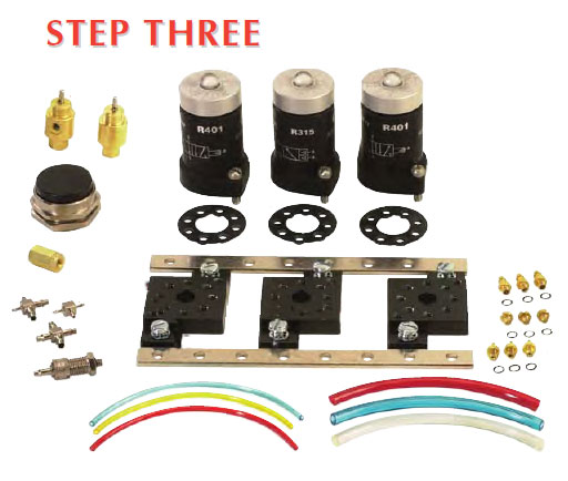
Components
Next, you need to gather the required components. Typically, the modular portion of a circuit consists of modular valves, subplates, mounting strips, 1/16” and 1/8” fittings, 1/16” and 1/8” hose, and the main air supply connect fitting.
This List is:
|
 |
|||
|
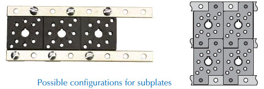
The next step is assembling the mounting strips (R-102) and subplates (R-101/R-101-M5).
|
 |
|||
|
Install the fittings into the R-101/R-101-M5 subplates using the octoport, octoport port coding, and pneumatic circuit diagrams. Generally, 1/16” hose or 5/32" is used for pilot ports and their adjoining lines and 1/8” hose are
for supply lines and cylinders.
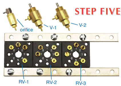 |
Looking at the Two-Hand, No-Tie-Down circuit:
1. Valve RV-1 has fitting 11752-5 (#10-32 to 1/16” I.D.
hose fitting) installed in ports 4 and 8
2. Fitting 11752-4 (#10-32 thd. to 1/8” I.D. hose
fitting) installed in ports 1 and 2 because port 1 is the
main air supply for the circuit and port 2 is the outlet.
3. On valves V-1 and V-2, fitting 11752-5 was installed
in both the inlet and outlet of each valve because both
valves are used for pilot actuation of valves RV-1 and RV-2.
Hose and barb sizes were picked with this particular pplication in mind. Both may vary to meet your needs. Feel free to contact our facility for technical support.
4. Being in a pilot line, the inline fixed orifice air choke
N-1 was fitted with an 11752-5 on one end and a UTO-2 universal “L” fitting on the other.
|
|||
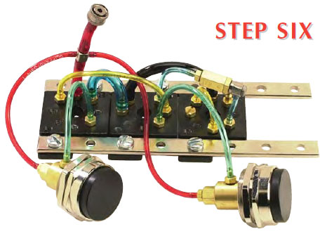 |
Connecting Hose
With the fittings installed, the circuit is ready for hose.
The color coding we use at Clippard is quite simple.
Red hose is used for all supply lines. For all other hose
as many different colors as possible are used in order
to facilitate circuit trouble shooting.
1. Supply lines - Red hose
2. The 1/16” I.D. fittings require URH1-0402 hose
3. The 1/8” I.D. fittings require URH1-0804 hose
4. The main supply line was fitted with a MJQC-CB4
which can be attached to any of the MJQC valve
bodies.
|
|||

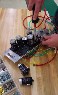
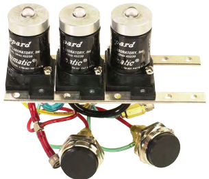
Modular Valve Hookup
The final assembly step is installing the modular valves and mounting gasket to the subplates.
Hose and barb sizes were picked with this particular application in mind. Both may vary to meet your needs. Feel free to contact our facility for technical support.
|
 |
|||