

The Logical Choice for Factory Automation
Category:
|
|
Original Article, July 2005 |
|
If you pump your own fuel at a self-serve gas station, chances are, you've usually relied on products manufactured by OPW, Cincinnati. That's because nearly 80% of refueling nozzles in the U. S. are made by Dover Corp.'s OPW Div. OPW is also a major player in swivel joints, vapor recovery components and systems, spill containment systems, and underground piping. At 250,000 ft 2, OPW's Cincinnati headquarters houses the industry's largest and most advanced research, development, and manufacturing facility. 
This press features features a pneumatic control that requires the operator keep both hands on pushbuttons—safe and out of harm's way. Implementing this and safety practices has helped contribute to more than a 90% reduction in workplace injuries.
In addition to its impressive R&D efforts, OPW has taken advantage of all the latest manufacturing techniques to maintain its enviable 80% market share—computer-aided design and manufacturing, rapid prototyping, automated machining centers, automated and robotic assembly, and quality certification and supply chain management programs. Not surprisingly, OPW relies heavily on pneumatics for a significant portion of its production operations.But what is surprising is an extensive use of low-tech pneumatic applications that have become instrumental to the efficiency, productivity, and safety of OPW's operations. You'll find a multitude of commonplace pneumatic systems throughout OPW's Cincinnati plant for accomplishing such routine functions as opening and closing of guards, operating presses, opening and closing of clamps, and providing motion for a variety of production machine components. You'll also find dozens of machines fitted with air logic circuits that ensure the safety of operators. In fact, fluid logic is essential to the operation of the automatic shutoff feature found on all self-serve refueling nozzles. (When fuel reaches a small tube inside the nozzle, air flow through the tube is blocked, which trips a mechanism that shuts of the fill valve.) Air logic breeds safetyAutomating operations, of course, increases productivity by increasing cycle times. And when done properly, says Jim Ruthemeyer, manufacturing engineering manager at OPW, automation improves safety and ergonomics of an operation as well. "We have four highly-skilled toolmakers within our Advanced Manufacturing Engineering Group who were instrumental in coming up with clever and effective ways to automate our operations. Personnel from our shop floor helped bring these ideas to fruition." A common application of air logic at the OPW plant are two hand, no-tie down controls. These controls are used whenever a reasonable potential exists for a machine to injure a worker—typically presses and clamps. The twohand,no-tie down control works by requiring an operator to actuate a pair of air switches simultaneously. Logic of the two-hand, no tiedown control requires the operator to press both switches at the same time—or at least within a narrow time period. If only one switch is pressed, or too long a time passes before the second is pressed, the machine cannot be operated until the control is reset and both switches pressed within the prescribed time period. Likewise, both switches must be released before the machine operation can be repeated. 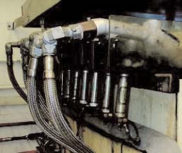 This setup ensures safety by preventing the simultaneous twohand operation requirement from being defeated. This could be done by securing one switch in the depressed position. Ruthemeyer says the two-hand, no-tie down control reduces workplace accidents because if operators must use both hands to operate machine controls, their hands cannot get in the way of potentially dangerous areas—within the range of presses or gripper jaws. "Obviously, our top priority is preventing workers from getting hurt. But from a business stand-point, injuries hurt productivity. If a machine would injure a worker, that machine could not be used until investigations—usually lengthy—were completed. Even then, machine modifications and subsequent testing would usually have to be performed." Ruthemeyer says management also must consider the actual cost of injuries, which can be in the form of Workers' Compensation payments, insurance premiums, and direct compensation. So reducing or eliminating workplace injuries not only benefits workers, but helps keep a lid on manufacturing costs by reducing machine downtime and labor costs. 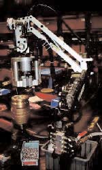
This fuel nozzle test rig uses pneumatic cylinders to actuate nozzles to failure—typically more than 1 million cycles. The rapid motion of pneumatics, plus the cushioning effects of compressed air, provide a motion dynamics that would be expensive and complicated to achieve using other technologies.
How much have these pneumatic machine controls improved safety? Ruthemeyer says that since OPW's safety team implemented these controls and other improvements-over a 7-yr period, workplace-injuries have been reduced from 24 injuries per 200,000 hr of work to less than two—more than a 90% reduction! Why compressed air? As with most machine automation applications, compressed air offers rapid motion, clean operation, high reliability, and longevity. The need for component longevity perhaps is best illustrated in OPW's test lab. Lab manager Mike Schubert explains, "We don't just test our components for a set number of cycles—we're looking for how many cycles to failure, which could be up to 1 million cycles. "When testing nozzles, we look for failure of any nature, whether it's any type of leak or a mechanical failure. The challenge is getting test rig components that may have to last up to 1 million cycles. So the air cylinders and other components that physically run the nozzles through the tests must outlive the nozzles. We've found the cylinders and valves we use from Clippard consistently provide the long, reliable operation we need." Clippard also provides training for OPW personnel. Ruthemeyer says that touring Clippard's facility usually generates ideas for automating operations with pneumatics. "Clippard is good at using pneumatics in their own plant to do everything from opening window blinds to clamping on machining centers. Seeing such a wide variety of applications opens your mind to the possibility of using pneumatics everywhere there is motion." Moreover, technical assistance is not limited to the just component manufacturer. Ruthemeyer says Isaacs Fluid Power, Mason, Ohio, is more than a component warehouse. "They provide the expertise to design perhaps 95% of our control circuits. Most of our circuits are fairly simple, so air logic is easier to keep organized and troubleshoot than PLCs. Plus, there are no wires or sensitive components to need the protection of an enclosure."
|
|
Be safe—use both hands 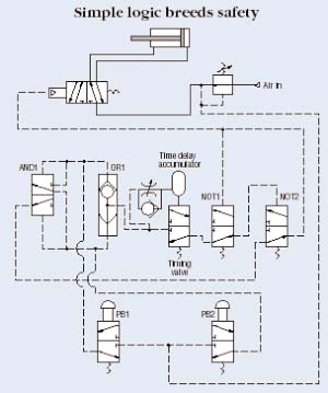 When push buttons PB1 and PB2 in the illustration are not actuated, the cylinder's directional valve receives no air to shift it, so the cylinder remains in its retracted position. The only condition that allows the directional valve to shift—thereby allowing the cylinder to extend—is when push button valves PB1 and PB2 both are pressed within a prescribed time period. If only PB2 is pressed, air flows to the lower port of the AND valve. But air pressure shifts the valve so that the lower port of the valve is blocked. Air from PB2 also goes through the OR element and initiates a timing function by charging the accumulator with compressed air. If PB1 is not shifted within a short time, pressure builds in the accumulator enough to overcome the opposing spring force of the Timing valve. With the Timing valve shifted, air flows through valve NOT1 to shift valve NOT2 closed. Once this occurs, depressing PB1 sends air through the AND valve to valve NOT2. But because valve NOT2 has closed, it blocks air flow from the AND valve. The same results occur if PB2 is pressed before PB1. This protects the operator because the cylinder will extend only if both pushbuttons are depressed within the relatively short time it takes to charge the accumula tor. They must remain pressed until the cylinder reaches the end of its stroke. The circuit also prevents keep ing a pushbutton depressed because both pushbuttons must be released to discharge air from the accumulator through the OR valve. To extend the cylinder, both push-buttons must be pressed simultaneously. Air from either one passes through the OR element to begin charging the accumulator. But applying air pressure to both sides of the AND valve allows air to pass through it, to the NOT2 valve. This event routes air to the cylinder's directional valve, causing it to shift, which extends the cylinder. A branch from the NOT2 valve output to the directional valve shifts the NOT1 valve closed, blocking air from accumulator. As long as both buttons remain pressed, the cylinder extends and holds. We thank Bud Trinkel, a fluid power consultant, for this explanation of an anti-tie down air logic circuit. Investigative team goes on air mission Because OPW makes such extensive use of compressed air, it's important for them to get the most power and productivity from their compressed air system. Therefore, when faced with a $20,000 quote to repair one of the plant's four reciprocating compressors made in the late 1960s, a team from OPW's maintenance department evaluated the plant's compressed air system, major components, and operation. The cost to repair a 35-year-old compressor seemed like a poor investment, but a replacement would cost $60,000. So the team's goals were to determine the best course of action regarding the plant's entire compressed air system. First, data was collected to determine header pipe capacity, which would indicate whether the system could deliver enough air to operate the plant without excessive pressure drop. Management discovered that compressor discharge pressure ranged from 69.5 to 96.9 psig, and averaged 82.2 psig. Pressure at the farthest point from the compressors ranged from 69.5 to 96.9 psig and averaged 82 psig. This was good news—it showed that the header piping system was capable of delivering air throughout the plant with less than 1 psig pressure drop. Next, system pressure was recorded throughout the work day. Results showed that pressure hit 90 psig or higher only 6.9% of the time, and stayed below 85 psig more than 75% of the time. The team determined that the wide fluctuations in air pressure were evidence that the compressors could not keep up with demand. Consequently, digital flow meters were installed in the main header pipe to find patterns of the plant's air usage throughout the day, as well as peak demands that caused the excessive pressure drops. Results revealed that flow never dropped below 200 cfm—even during periods when no production was occurring! This was clear evidence of leaks generating false demand. Finally, data was collected comparing compressor power to air volume output to determine compressor efficiency. Constant throttling to load and unload the compressors meant the compressor put out only 2.4 cfm/hp. By also measuring current draw of the compressor motors, the team determined the cost of electricity to operate the compressors was $41,875. However, Ruthemeyer says reciprocating compressors do not operate effectively with frequent loading and unloading—they operate most efficiently at full load, which also reduces mechanical wear. In fact, when in good operating condition—and without frequent on-off cycling—these compressors are capable of producing 4.3 cfm/hp. Consequently, appropriate action would include revising the loadunload routine of the compressors. Cost-cutting solutions Realizing that the most savings could be gained by modifying their current system, the team decided to repair the old compressor. To their delight, they found that the compressor's cylinder head was not cracked, which allowed them to forego most of the $20,000 repair bill or the $60,000+ for a new compressor. They also eliminated multiple leaks in the piping system and end use devices. This leak detection and elimination project continues, with of goal of getting leakage below 25 cfm. The team also had clogged elements replaced in the air intake filters and in a dryer (which, in itself reduced pressure drop from 30 psid to 5 psid). After performing several other modifications, the team determined that the wide fluctuations in pressure could be smoothed out by limiting pressure in the plant to just what is needed. Consequently, a large pressure regulator was installed in the main supply line and set at 85 psig. This action reduced false demand from leaks and by all unregulated devices. It also improved the efficiency of the compressors by allowing them to remain loaded for longer time periods because the system's pair of 750-gal receiver can now act as an energy buffer by storing compressed air. (This is the same concept used in hydraulic systems that use accumulators to supplement pump flow by storing pressurized hydraulic fluid.) Ruthemeyer says the plant's compressed air demand was slashed by more than two thirds—from 334 cfm in July 2004 to 108 in November. Also, compressor efficiencies were nearly doubled, and the system is reliable enough to run unattended for long time periods. He explains that the project has reduced the annual electric usage to compress air by $29,000—from $43,000 annually to $14,000. Combining this with additional savings from lower maintenance and other associated costs, OPW realized a net savings of $90,000 and expects a recurring annual savings of $40,000 or more. |


