Building a Billion-Cycle Valve
Here's how engineers used advanced software and innovative manufacturing techniques to produce a next-generation, high-flow valve. Like most everyone today, machine builders want more for less. That certainly holds for users of pneumatic valves, who are clamoring for higher flow capacity, but not at the expense of buying a larger valve. At Clippard Instrument Laboratory, Cincinnati, such demands have spurred the development of a new line of two-way solenoid valves called the DV. Its unique construction builds on technology developed for the company's proven and reliable EV valves. But it provides five to six times more flow in an equally compact design. And, its rated life exceeds 1 billion cycles. Engineering Challenges Though a serious design constraint, small size is a must because users rely on banks of these valves to handle a variety of tasks, he explains. "They're used in packaging equipment, medical devices, analytical instrumentation, and many other places. Industrial applications typically have multistation manifolds where valves are mounted as close together as possible to minimize space requirements. Thus, the DV valve's OD couldn't exceed three-quarters of an inch." The first obstacle for the Clippard engineers was designing a solenoid coil that fit the available envelope and could generate sufficient power to shift the valve at high pressures — or determine it was impossible. Product specs called out maximum size, minimum power levels, and maximum flow at standard pressures of 100 psi. And response time had to be in the 10 to 15-msec range to permit high-speed operation. The question was, how much magnetic force could a coil generate, and how big a magnetic puck was needed to pull against a half-pound preload? "With coil design, it's all about amp-turns," explains McBreen. "You get the most bang for your buck by wrapping out and growing your diameter, as opposed to growing taller." Coil technology hasn't advanced much since the days of the EV's development, so McBreen found no magic bullet in the latest generation of solenoids. "It's still wrapping wire around a spool," he says. They did consider voice-coil actuators, but found them too expensive and with unproven long-term reliability. "It was in our design's best interest to stay with a standard wound coil," says McBreen. Faced with so many variables, and so many iterations, Clippard engineers developed a Coil Calculator software program to streamline the design process. It let them optimize the coil in relatively short order. "We're basically designing a bobbin," says McBreen, "and we know the inner and outer diameter of the spool, how tall it is, and the wall thicknesses. The software lets us plug in the geometry and then enter different wire gauges. It shows us how many amp-turns we can get with a 34-gauge wire, a 32-gauge wire, and so on. We key in on the combination that gets us close, then make finite changes to the bobbin geometry to tune it in." They chose to develop the program in-house, rather than rely on off-the-shelf software, because they had very specific goals. It's like buying an FEA package with lots of options that you don't need, and isn't well suited to your problem, he explains. "The Coil Calculator gave us exactly what we were looking for, it was obviously the way to go." Engineers used the calculator in tandem with EMS, a 3D electromagnetic field simulator program from Montrealbased ElectroMagneticWorks. It let them tweak the resulting magnetic circuit, with impressive results. "I was shocked at the accuracy," admits McBreen. The first prototype met all physical requirements and performed to within 5% of predictions, which is in line with standard coil tolerances. Higher Flow They examined many different orifice and channel shapes in the quest to maximize flow. For example, certain nozzle geometries, and radii on the nozzle edges, gave smoother, more-laminar conditions that resulted in consistent and higher flow. An added benefit was lower friction between the orifice and mating nozzle seal, which reduced preload and wear. 
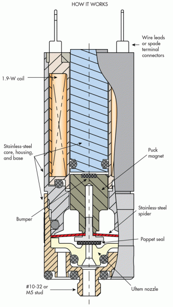
The DV is a normally closed valve. The poppet with an overmolded seal presses against the nozzle and closes off flow. Energizing the solenoid lifts the magnetic puck towards the core until it bottoms out against the bumper. In the manifold-mount version, air then flows through the #10-32 port, through the orifice, and into the internal chamber. A series of slotted holes surround the molded nozzle, permitting air to flow out to the manifold. Engineers relied on both computational fluid dynamics analysis, in this case Flow Simulation CFD from Dassault Systémes SolidWorks, based in Waltham, Mass., as well as on physical testing—validating concepts with machined prototypes. CFD proved to be an excellent tool for modeling flow through individual valves and examining various options, says McBreen. However, simulating a bank of manifold-mounted valves was rather time consuming, he admits, as there are so many pathways to consider. Spider Spring Getting the configuration just right required intensive FEA analysis in SolidWorks on various spider designs. "We wanted the legs as long as possible, to get the longest stroke within our space limitations," says McBreen. Thus, the number, shape, length, and layout of the legs, the radii of transitions, and many other factors were studied and adjusted to come up with the proper stroke and spring rate—while keeping stress levels sufficiently low to ensure extremely long life. The spider spring, with its long, narrow and curving legs, would be difficult to machine or fabricate by stamping, but it is pretty simple to etch, he notes. The process starts with a flat sheet of 0.020-in.-thick 17/7-PH stainless steel, which is then chemically etched to the final configuration. A finishing operation removes stress risers and gives it a glasslike surface. The process holds tolerances on some features to ±0.001 in., so there is little variation from part to part. That helps ensure consistent performance from one valve to the next. Testing, Testing McBreen's main concern was that the overmolded poppet seals would peel off the base metal over time, but that was never an issue. However, one unforeseen dilemma on an early prototype was the appearance of fretting corrosion between the magnetic puck and housing. The initial design mandated an extremely small gap between the two parts, to take full advantage of the available magnetic field, McBreen explains. "Apparently, it was a bit too close." 
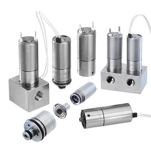
The compact DV is a two-way solenoid valve that provides five to six times the flow of previous versions. 
The spider spring shifts the valve when the solenoid deenergizes and has a stroke of only 0.018 in. Fixing the problem wasn't a simple as merely widening the gap, however. "If you make the clearance too big, then you lose a percentage of your magnetic force." He again turned to the EMS software to refine dimensions and ensure the puck stays centered and glides with minimal friction—all while maintaining the needed magnetic-field strength. Such setbacks are inherent to engineering, says a pragmatic McBreen. "It's part of the optimization process. Analysis only shows you so much and gets you in the right ballpark. That's why you test it, to find out what relative changes you can make to improve the end product." Manufacturing Issues Ensuring the DV is easy to manufacture and assemble was also a prime concern from the beginning. One example McBreen cites is opting for a molded nozzle, versus a machined one. Machining small orifices in stainless steel and holding extremely tight tolerances is difficult, and the parts take too long to make. Instead, a key supplier molds the nozzles from dimensionally stable Ultem and holds ±0.001 in. on the ID and other critical dimensions. And they tightly control the process to ensure excellent repeatability, he says. The plastic nozzle also lets manufacturing personnel pop in a radial seal by hand, and it seats against the housing and nests in proper relation to the spider. The subassembly gives the necessary preload with near-zero friction on liftoff. Assembling the DV involves simple press fits with no shimming. The three subassemblies are put together using simple tools, and every valve is automatically tested prior to shipping to the customer. Compared to the EV valve, the DV's streamlined manufacturing procedures save several minutes of production time for each part – which adds up to sizable time savings in highvolume production. Product Specs It's suitable for service with air and other compatible gases, and it is currently being tested with water. The valve base is made of 303 stainless steel, and all the magnetic components are 430F stainless steel. Other "wetted" materials include Ultem and polyphenylene sulfide (PPS). Ultem is a thermoplastic polyetherimide resin with outstanding elevated thermal resistance, high strength and stiffness, and broad chemical resistance. PPS, in similar fashion, has outstanding chemical resistance as well as thermal and dimensional stability. Seals in the DV are typically Buna, but FKM, silicone, and EPDM are available on request. The valve has rather large flow passages and is quite dirt tolerant, says McBreen. It runs fine on air filtered to 40 μm and offers an important user-friendly feature: the valve is easy to disassemble and clean. Control voltages are typically 12 and 24 Vdc, but many users design their own circuitry. One example is hit/hold actuation which energizes the valve momentarily with its rated voltage, and then reduces it by approximately 33% to hold the valve position. Some even run off rectified alternating current. Rated power consumption is 1.9 W. Both manifold and cartridge mounting options are offered, and the valve has #10-32 ports and a 0.75-in. body. Clippard is also producing a metric version for marketing worldwide. It has M5 ports and a 19-mm body. Markets & Applications He ticks off a list of potential applications, such as in medical devices like blood-pressure cuffs, for analytical instrumentation, gas chromatography, and leak-decay test systems. In manufacturing settings, banks of valves are well suited for controlling production machines and packaging operations—applications that tend to have lots of cylinders and actuators. A fully ported three-way version of the DV is slated for introduction this fall, and a proportional valve is in the works. |


