MME Electronic Valve Installation & Operating Instructions
| Installation of MME 3xxx- and 4xxx- | ||
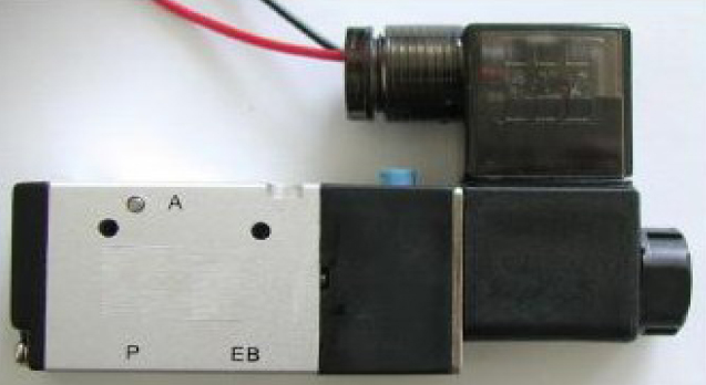
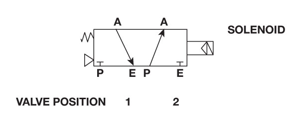
Connecting the MME-3xxx- 3-way valve inlet and outlet as shown in the diagram: |
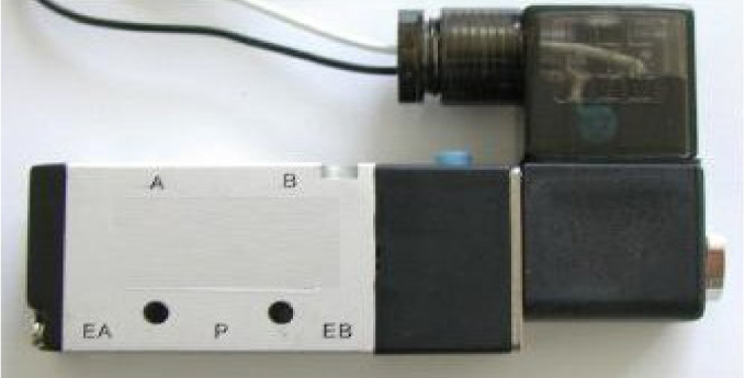
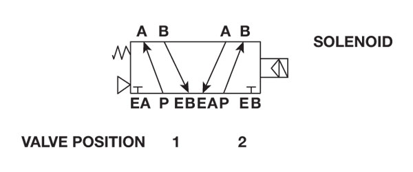
Connecting the MME-4xxx- 4-way valve inlet and outlet as shown in the diagram: |
|
Electrical Connections |
||
|
To connect the DIN coil: 1. Remove the Phillip screw from the plastic housing and unplug it from the DIN coil. 2. From the screw opening, use the screw to push the terminal block out of the plastic housing. 3. Note the 1, 2 and ground markings on the underside of the DIN enclosure. 4. For DC DIN Coil, connect 1 to positive, 2 to negative. 5. For AC DIN Coil, connect 1 to HOT wire, 2 to NEUTRAL wire, and if required connect ground to ground wire. |
To connect Grommet coils or DC Coil: 1. If the DC solenoid coil has a red and a black wire, connect positive to RED wire and negative to BLACK wire. 2. If the DC solenoid coil has two same color wires, connect positive to one of the two wires and negative to the other wire. AC Coil: 1. If the AC solenoid coil has a black and a white wire, connect the HOT wire to the BLACK wire and NEUTRAL to the WHITE wire. 2. If the AC solenoid has two same color wires, connect the HOT wire to one of the wires and the NEUTRAL wire to the other wire. |
|


